 SGM41527.pdf
No.10655
● 4A Synchronous 1.6MHz PWM Charger
Cycle-by-Cycle Current Limit
Integrated 24V Switching MOSFETs
Integrated Bootstrap Diode
Digital Soft-Start
● Up to 95.2% Charge Efficiency
● 30V Absolute Maximum Input Voltage Rating with
Adjustable Over-Voltage Threshold
● 4.5V to 22V Input Operating Voltage Range
● Automatic Power Path Selector (Battery/Adapter)
● Dynamic Power Management (DPM)
● Battery Charge Voltage Select 2-, 3-, or 4-Cell with 4.2V/Cell
● Less than 18μA Battery Current (No Adapter)
● Less than 1.3mA Input Current (Charge Disabled)
● High Accuracy
±0.5% Charge Voltage Regulation
±4% Charge Current Regulation
±4% Input Current Regulation
● Thermal Regulation (Current Limit for TJ = +120°C)
● Thermal Shutdown
● Battery Thermistor Sense Hot/Cold Charge Suspend
● Input Under-Voltage Lockout (UVLO)
● Input Over-Voltage (ACOV) Protection
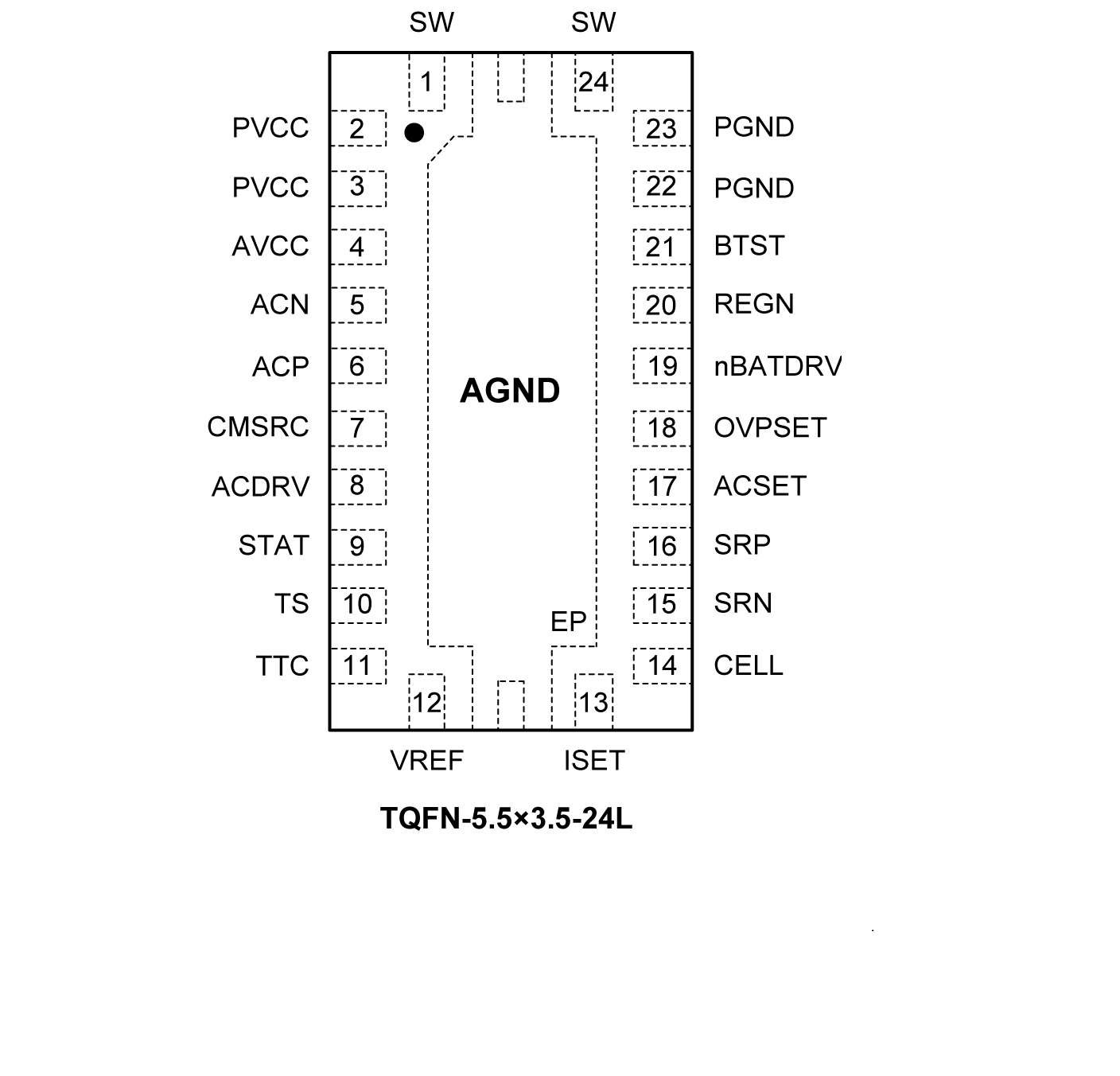
The SGM41526 and SGM41527 are stand-alone Li-Ion and Li-polymer battery chargers and power path management devices with integrated PWM switches for the charger. They also include gate drivers for external power path selector MOSFETs. The synchronous PWM controller runs at a fixed frequency (1.6MHz) and is capable of accurate regulation of charge voltage, charge current and input current. They are capable of continuous battery pack temperature monitoring in which the charge is only allowed when the temperature is within the desired range. The SGM41526 can charge 2-, 3- or 4-cell (selected by CELL pin); while the SGM41527 has an adjustable charge voltage for up to 4 cells. In the SGM41527, the FB pin is used for charge voltage regulation (feedback) using an internal 2.1V reference and comparator.
Typically, a full battery charging cycle has three consequent phases: pre-conditioning, constant current and constant voltage. The charge current is small during the pre-conditioning phase in which battery is heavily depleted. When the battery voltage exceeds a threshold voltage, the charge current increases to its maximum (fast charge current) until the battery voltage reaches its regulation level. Then the voltage is regulated and charge current drops. The starting phase is determined by the initial battery state of charge sensed through the battery voltage. Charging is terminated when the charge current drops below 10% of the fast charge value. A programmable safety charge timer is provided to prevent prolonged charging if for any reason it is not naturally terminated. A charge cycle is automatically started (or restarted) if the battery voltage falls below a predetermined threshold.
